CO₂ Capture Project

CO₂ Capture and Storage

CO₂ Capture and Storage (CCS) involves capturing the CO₂ from fossil fuels before, during or after combustion and permanently storing it in deep geological formations (such as depleted oil and gas fields and deep saline formations).

Power station, oil refinery, cement kiln or gas plant

Water Table

Extra barriers of steel casing and cement around the well are used to protect groundwater. The number of barriers varies according to the different geological conditions.

Aquifer

(ground water can be found 100s of meters deep)

Barriers of cement and steel casing protecting aquifer

Surface casing

Injection casing

Well tubing carrying
injected CO₂

Geological formations diagram

Computer modelling of oil field characteristics - the same
techniques are being used to map sites suitable for CO₂
storage. Image courtesy of BP

Site Selection

The oil and gas industry has decades of experience understanding and assessing sites kilometers deep underground. The latest technology to map oil and gas fields is now being used to assess sites suitable for CO₂ storage. The most effective way to ensure permanent safe storage is to choose sites of sufficient depth (typically deeper than 800 meters) with adequate capacity and an overlying sealing system to ensure containment of fluids.

Depleted hydrocarbon reservoirs, such as oil and gas fields, are highly suited to such geological storage of CO₂. Other potential storage sites are saline formations - permeable rock formations, which contain salty waters in their pore spaces - and unmineable coal beds.

As CO₂ is injected the pressure increases with depth.
Between 800-1000m the CO₂ is naturally compressed to less than 1% of its surface volume - giving it a density more similar to a liquid than a gas.

Geological formations could provide storage space for 2,000,000,000 metric tons of CO₂ a year - According to the Intergovernmental Panel on Climate Change (IPCC)

Capture

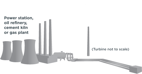
Over 90% of the CO₂ produced by fossil fuels at large fixed installations can be captured and prevented from reaching the atmosphere. Three main technology types - pre-combustion, post-combustion and oxy-firing - are available, allowing CO₂ to be captured from industrial processes such as power generation, oil refining and cement manufacture.

The component parts of the pre-combustion technology exist today at commercial scale; the challenge now is to integrate these in a power application.

Post-combustion can be installed on both new and existing power plants - of vital importance given that the average power plant operates for 40 years. The challenge around post-combustion is to scale-up the technology for use in commercial power applications and integration.

Structural Trapping

Fluid CO₂ rises to the top of the formation until it reaches an impermeable layer of caprock. This layer securely traps the CO₂.

Residual Trapping

CO₂ moves up through the geological storage site towards the caprock, some of it is trapped in the microscopic pore spaces in the rock, similar to air becoming trapped
in a sponge.

Dissolution

Over time, CO₂ will begin to dissolve in the surrounding salty water, making it become heavier and sink.

Mineral Trapping

Mineral storage occurs when the CO₂ binds chemically and permanently with the surrounding rock.

US pipeline infrastructure has the capacity to safely and reliably carry 50,000,000 tons of CO₂ a year.

US pipeline infrastructure has the capacity to safely and reliably carry 50,000,000 tons of CO₂ a year.

Transport and Injection

Today CO₂ is transported by truck, ship or pipeline. However, to transport the large amounts of CO₂ from power plant emissions, pipelines are the only practical solution. This pipeline transportation process is well understood as CO₂ pipelines have been used since the 1970s, transporting large volumes of CO₂ to oil fields for enhanced oil recovery (EOR).

Injection

The oil and gas industry has years of experience injecting CO₂ underground into geological formations, a process used to enhance oil recovery. Millions of tons of CO₂ are injected annually under regulations which protect local communities and the environment. As oil and gas have become more difficult to access, the industry has rapidly developed precise drilling practices to meet the challenge. This technology is being deployed to securely store CO₂.

A storage formation can have multiple layers of impermeable caprock

Storage diagram

Storage

Mechanisms

Oil and gas have remained trapped underground for millions of years. The same natural conditions allow injected CO₂ to be stored securely. Once CO₂ is injected deep underground (typically more than 800 meters) it is absorbed and then trapped in minute pores or spaces in the rock structure. Impermeable caprock acts as the ultimate seal to ensure safe storage for millions of years.

A storage formation can have multiple layers of
impermeable caprock.

There are four main storage mechanisms:

  • - Structural Trapping
  • - Residual Trapping
  • - Dissolution
  • - Mineral Trapping
Monitoring image

Satellite imaging, In Salah CCS project, Algeria
Image courtesy of BP

Monitoring

A wide array of monitoring technologies have been used by the oil and gas industry to track fluid movement in the subsurface. These techniques are readily adaptable to CO₂ storage to monitor the behaviour of CO₂ underground. For example, seismic surveying provides an image of the subsurface, often allowing the behaviour of stored CO₂ to be mapped and predicted. Other monitoring technologies include down hole and surface CO₂ sensors. New technologies such as satellite imaging, which can detect movements of less than 1mm in the Earth’s surface, are also being developed.

0m Depth arrow